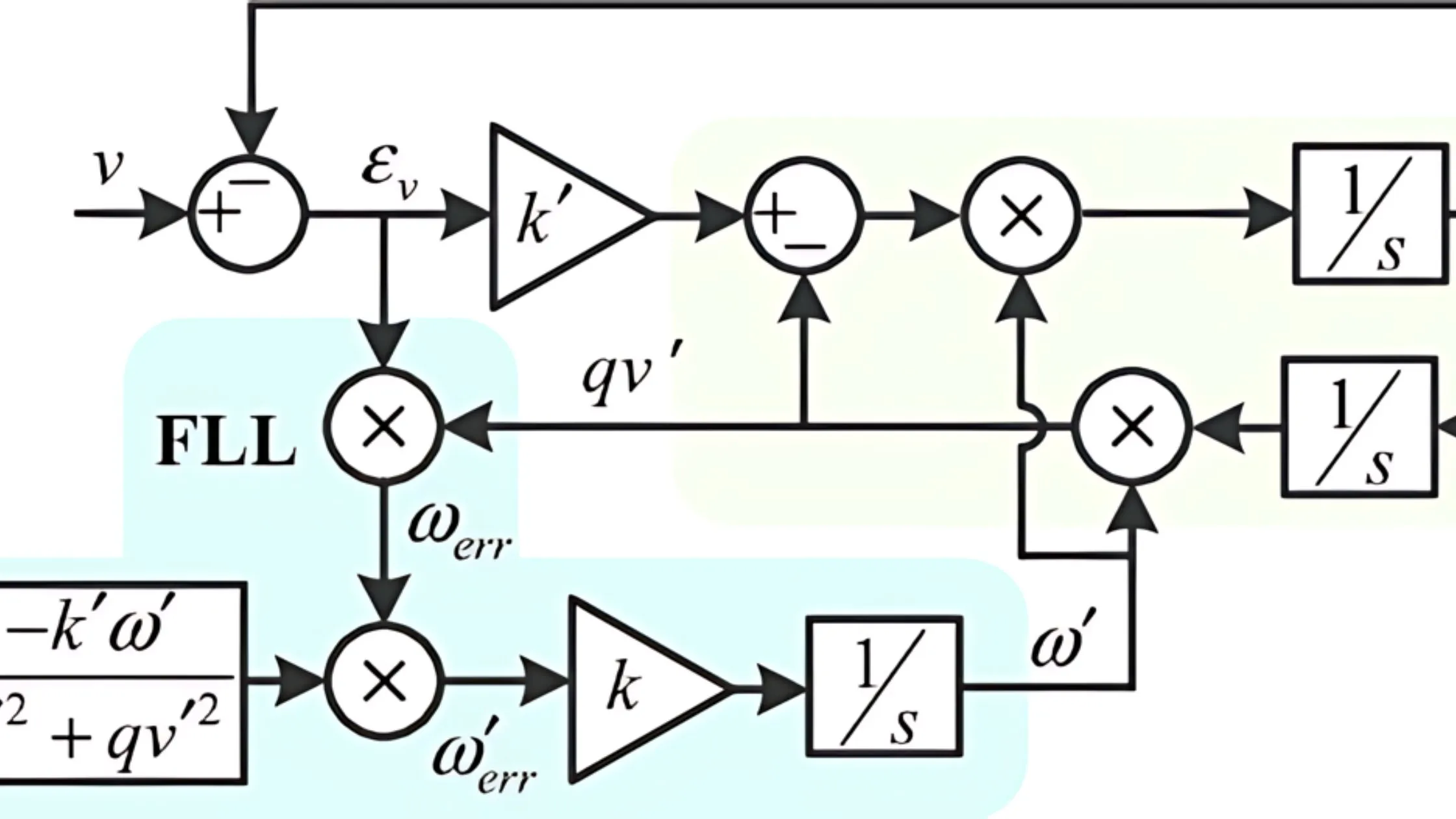
A frequency-locked loop, commonly known as FLL, is an electrical circuit that guarantees one signal matches the frequency of another. You can envision a small conductor always adjusting the radio dial slightly. It works in a fashion where it keeps comparing the frequencies of an output signal and reference signal continuously. Every difference is captured and applied to modify the output frequency until they match.
Frequency Locked Loops have a critical role in stabilizing frequencies of devices such as clocks or radio transmitters, even assisting with signal extraction from noisy communication channels. FLLs can be seen as similar to Phase-Locked Loops, but they only lock onto frequency.
A Block-by-Block Breakdown
The main part of a frequency-locked loop is its linked components.
Output: This represents the frequency that FLL wants to copy. It gives a goal for the output signal to match.
Frequency Error Detector: This is a very observant watchdog that keeps comparing the frequencies of input signal and FLL’s own output. Every difference is translated into an error code signal – if there’s more disparity, then the mistake becomes stronger.
Loop Filter: Think of this like a language converter. It takes the rough error signal from FED and makes it soft, removing extra noise. This part makes sure that changes in the output frequency are smooth and steady.
Voltage Controlled Oscillator: This part is the most important in FLL, making the output signal. The frequency of VCO gets set by the loop filter’s output that is like a control voltage. The FLL adjusts this voltage and makes small changes to keep its own output signal’s frequency matching with the reference’s one.
Applications of FLLs
Frequency-locked loops are very important in different uses, especially for situations where having exact frequency control is crucial.
Signal Recovery in Communication Systems: Consider a faint radio signal hidden among static. Frequency-locked loops can be utilized for separating the wanted signal from a noisy channel. When locked to the reference frequency of the desired signal, FLLs become effective filters that remove unwanted noise at varying frequencies.
Stabilizing Frequency in Electronic Devices: The operation of electronic devices such as clocks and radio transmitters is dependent on consistent frequencies. FLLs have the task of continuously observing and modifying the frequency of internal oscillators present within these gadgets, making sure they sustain precise output frequencies that can be trusted always.
FM Demodulation: In radio transmitting through Frequency Modulation, the data is encoded by changing the frequency of the carrier signal. Certain FLLs can be employed to restore original info signal by demodulating FM signal. They basically get locked onto the carrier’s middle frequency and extract info that has been recorded in variations of frequency.
Synchronization of Power Grids: To keep frequency in power grids constant, we can use FLLs for matching the frequencies of various generators. This helps in giving steady power.
Acquiring Sensor Data: For some sensors, they use oscillating signals to transmit data. FLL can be employed in order to demodulate these signals, taking out the important information which is encoded within the frequency variations.
FLL vs. PLL: Understanding the Similarities and Differences
Phase-Locked Loops are very similar to Frequency-Locked Loops, having the same main purpose: attaining frequency synchronization. They also utilize a feedback loop for modifying an output signal so it aligns with a reference signal. However, PLLs go beyond this level. FLLs only handle matching of the frequency, whereas PLLs manage both frequency and phase alignment with the reference signal.
This extra phase synchronization gives PLLs a higher level of accuracy but also adds some complexity compared to FLLs. Think about an FLL that makes sure two orchestras play at identical tempo, while a PLL confirms they not just play at equal pace but also begin and conclude notes together.
Advantages of FLLs
Frequency-locked loops have two main benefits, which put them ahead. First and foremost, their design is naturally simpler in comparison to the closely related phase-locked loops. This result provides a big advantage, quicker acquisition. FLLs rapidly link to the needed reference frequency, making them suitable for tasks requiring fast synchronization.
Limitations of FLLs
They only lock onto the frequency, not the phase. This means the FLL output might match the reference signal’s frequency exactly, but the peaks and valleys (phase) could be misaligned. For applications where both frequency and phase alignment are crucial, Phase-Locked Loops are the preferred choice.
Advanced FLL Techniques
Even though the main concepts of Frequency-Locked Loops are about keeping frequency in tune, FLLs’ world is more than just these fundamental functions. Let’s take a look at few complex techniques that explore the limits of what FLL can do:
Type 1 vs. Type 2 FLLs
Different FLL architectures have been classified into two types, each having unique advantages and disadvantages:
Type 1 FLL: This has a simpler design and can be acquired faster. But, it has less ability to reject noise and might find it difficult to handle big starting frequency errors.
Type 2 FLL: They are of a more complicated design, giving them superior ability to ignore noise and deal with bigger first frequency offsets. Nevertheless, they might have acquisition times that are somewhat slower than Type 1 Frequency-Locked Loop.
Digital FLLs: The regular FLL uses analog parts. But, the increase in digital signal processing has made possible digital FLLs. These FLLs, they put into practice the main workings with software algorithms that work on a digital processor.
Designing and Implementing a Frequency-Locked Loop
To design and apply a Frequency-Locked Loop, we need to think about some things. First is the properties of reference signals that will impact design choices for FLL. Secondly, picking the right parts for frequency error detector, loop filter and voltage controlled oscillator are very important in getting desired performance.
At the end, the design decisions will be influenced by performance factors such as lock time and noise rejection. When these elements are considered thoroughly, engineers can customize FLL to match their application needs precisely.
They are not the most complex technology, but in various applications their ability to lock frequencies is very important. From communication systems to radio transmitters and much more, Frequency-Locked Loops bring simplicity and speed which makes them a strong choice for many situations. When you listen to clear radio signals or experience smooth data transmission, remember the quiet hero working behind the scenes – Frequency Locked Loops.


